
Bluetooth RPM Letterboard v2.0
- Pedro Martin
- Jan 26, 2022
- 9 min read
Second iteration of a Rapid Prompting Method (RPM) letterboard with capacitive touch sensors & Bluetooth connectivity

Things used in this project:
Hardware components
Adafruit HUZZAH32 – ESP32 Feather Board x 1
Adafruit Capacitive Touch Sensor Breakout - MPR121 x 3
Adafruit Small Enclosed Piezo w/Wires x 1
Adafruit Lithium Ion Polymer Battery - 3.7v 350mAh × 1
Adafruit On-Off Power Button / Pushbutton Toggle Switch x 1
Adafruit STEMMA QT / Qwiic JST SH 4-pin Cable - 100mm Long x 3
Flexible 28AWG Tinned Copper Silicone Stranded Wire x 1
Copper Foil Tape with Conductive Acrylic Adhesive x 1
M2.5 Nylon Hex Spacer Standoffs Screws Nuts Assortment Kit x 1
Software apps and online services
Arduino IDE
Espressif Arduino ESP32
T-vK's ESP32 BLE Keyboard
Hand tools and fabrication machines
Soldering iron (generic)
Dupont Crimping Tool Kit
Precision Wire Stripper, 30-20 AWG
Hot Glue Gorilla Dual Temp
LED Lighted Magnifying Third Hand - Five Arms
Digital Multimeter
Story
Background
This is the first "production" version of my prototype (www.hackster.io/pedro-martin/bluetooth-rpm-letterboard-7f2ff4).
In a nutshell (full story in the prototype link): The Rapid Prompting Method (RPM) is a technique developed as a vehicle for non-verbal autistic children (and adults) to communicate, that, in effect, unlocks them from a silent isolation and can prove that they are intellectually intact. It can be life-changing for the autistic child and for the people who love them.
RPM uses a letterboard for the student to spell and communicate during the interaction with the facilitator. There are a lot of sensory variables involved. Practice, patience and consistency are only a small portion of what's required.
This letterboard that acts as a Bluetooth keyboard, sending its output to an iOS device that provides typing feedback through its text-to-speech functions.
Design Considerations
The Board
A first requirement is to recognize the selected letter by a very soft touch, so capacitive touch sensing was chosen. This also allows for custom printed faceplates. Also, it has to be very light for comfortable use in one hour sessions (this version weighs in at 200 grams, similar to a small iPhone. Compare to 600 to 900 grams of a Bluetooth keyboard). Finally, it has to survive constant manipulation by the facilitator.

The Electronics
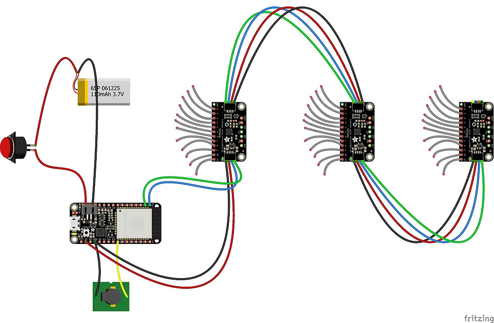
I chose an ESP32 as MCU because of its speed, BLE and Wi-Fi capabilities (plus a large community for support and libraries). To handle the capacitive touch functions of the letterboard, I chose the MPR121 breakout boards from Adafruit: they are relatively well documented, well developed, and, high quality (as is their HUZZAH ESP32 Feather board). Communication between the three MPR121's (for a total of 36 sensors) and the ESP32 is via I2C. I added a piezo buzzer to provide status feedback in conjunction with the HUZZAH32's built-in red LED. Finally, a 350mAh LiPO battery feeds the ESP32 via a simple On/Off mechanical switch.
Assembly
The base of the board is made from 5mm foam board (rigid enough and lightweight). The front side has 1 sq. inch adhesive copper tape as the touch sensor for each letter (seen here in mid-assembly, with the wires coming in from the back side)

The back side has 28 gauge stranded wire leading each copper sensor to the corresponding MPR121 breakout board in which I soldered right angle headers to receive the female Dupont connector of each wire. The position of the MPR121´s allow for the shortest path to each sensor: this minimizes capacitive interference and maintains capacitive sensitivity (see Code Considerations and application note AN3863 in RESOURCES for more information on this topic). The I2C bus and VCC/GND connections are made with STEMMA QT cables.
The HUZZAH32 is soldered to a perfboard for better installation on the foam board. It also has right-angle headers to receive female Dupont terminals. Note that I added on the back side, a 1/2" MDF reinforcement at the top and left sides for better survival of daily manipulation.

In both cases (front & back), I designed the layout in PowerPoint and printed these layouts on adhesive vinyl which were then added to both sides of the foam board.

In order to isolate the I2C & VCC wires (STEMMA QT cables) from the 28 gauge stranded wires connecting the copper sensors to the MPR121's (to avoid noise on both), I added a transparent plastic layer, with the STEMMA QT wires on top and the sensor wires below the plastic layer and glued to the foam board.

Finally, I added a back cover from the same foam board with a transparent plastic window to see the (green) status LEDs of the MPR121's. I also added a little foam where the hand will hold the board for enhanced comfortability.

Code Considerations
To increase the capacitive sensitivity, I changed the CONFIG1 & CONFIG2 registers in Adafruit_MPR121.cpp. This alters the number of samples, the duration of each sample and other associated filtering parameters. The downside would be a reduced available typing speed, that, for this use case, is not a problem. (See the links for application notes AN3889 and AN3890 in "Additional Resources")
//default values = 16uA charge current 6 samples FFI
//writeRegister(MPR121_CONFIG1, 0x10);

//new values = 32uA charge current 6 samples FFI
writeRegister(MPR121_CONFIG1, 0x20);

//default values = 0.5uS CDT, 1ms sample interval, 4 samples SFI
//writeRegister(MPR121_CONFIG2, 0x20);

//New values = 1uS CDT, 1ms period, 10 samples SFI
writeRegister(MPR121_CONFIG2, 0x52);
Periodic Sensor Reset
Any capacitive touch sensor can be affected by changing electromagnetic circumstances in the environment (i.e. humidity, relevant bodies nearby, etc.). Because of the heightened capacitive sensitivity programmed (previous point), these environmental circumstances can negatively impact the response of touch events. To mitigate this, I take advantage of the MPR121 reset function, which recalibrates the sensors for the then existing environmental conditions. So the first reset occurs at minute 3 and every 7 minutes thereafter.
void ResetSensors()  {
  TS1.begin(0x5A); TS2.begin(0x5B); TS3.begin(0x5C);
  TS1.setThresholds(0x19,0x05);
  TS2.setThresholds(0x19,0x05);
  TS3.setThresholds(0x19,0x05);
}

void ChkResetCapSensors() {
  int UpTime = int(millis()/1000/60); //--uptime in minutes
  int MinFactor = UpTime % 7; //--divisor is number of minutes between TSs resets
  if (MinFactor != 3) {CapsResetFlag = false;} //--first reset at compared minute
  else
    if (!CapsResetFlag) {
      ResetSensors();  // Buzz(1);
      CapsResetFlag = true;}
}
System Status Codes
The combination of Piezo Buzzer sounds and HUZZAH32's on-board RED LED provide the following status information

void Buzz(int BuzzType) {
  switch (BuzzType) {
    case 1: ledcWriteTone(0,1000); delay(100); ledcWrite(0,0);
            break; //--TS1 is up or scheduled TS reset run
    case 2: ledcWriteTone(0,1500); delay(100); ledcWrite(0,0);
            break; //--TS2 is up
    case 3: ledcWriteTone(0,2000); delay(100); ledcWrite(0,0);
            break; //--TS3 is up
    case 4: ledcWriteTone(0,1100); delay(10); ledcWrite(0,0); delay(1000);
            digitalWrite(A12, HIGH); ledcWriteTone(0,400); delay(10); ledcWrite(0,0);
            delay(1000); break; //--waiting on BLE pair
    case 5: ledcWriteTone(0,900); delay(300); ledcWriteTone(0,400);
            delay(700); ledcWrite(0,0); break; //--BLE pairing achieved
    case 6: digitalWrite(A12,HIGH); ledcWriteTone(0,100); delay(2000);
            ledcWrite(0,0); break; //--fatal error, must reboot manually
    case 7: ledcWriteTone(0,100); delay(300); ledcWriteTone(0,50);
            delay(700); ledcWrite(0,0); break; //--error, autorestarting TS's
    case 8: digitalWrite(A12,HIGH); ledcWriteTone(0,1500); delay(40);
            ledcWrite(0,0); digitalWrite(A12,LOW); break; //--low battery
  }
}
Battery Level
After comparing with multimeter readings, the correct battery voltage is achieved applying a correction to the internal pin (A13) reading with this formula:
void ChkBattery() {
  float battRead = analogRead(A13); //--or analogRead(35)
  battRead = ((battRead*2) / 4095 * 3.3 * 1.096);
  if (battRead < 3.3) {  //3.3v as base for beep
    ++counter;
    if (counter > 80) {
      Buzz(8);
      counter = 0;    }}
}
Available Memory on the MCU
To reduce memory requirements, I'm using NimBLE. T-vK's BLE Keyboard reports a bug with the #define statement in ArduinoIDE (but not so in PlatformIO) when using NimBLE. The workaround: Edit BleKeyboard.h and put #define USE_NIMBLE before the first line. Edit BleKeyboard.cpp and move line 17 before the first line.
Another option is to change the HUZZAH32's default memory partition, for example, choosing No OTA or Minimal SPIFFS

ESP32 Arduino Core
Releases of Espressif's Arduino Core for ESP32 prior to 2.0 have an issue with I2C. The Arduino IDE will operate with the latest stable version, but take caution that PlatformIO (as of this update) is still using 1.0.6.
Additional Resources
These three application notes from Freescale Semiconductor (manufacturer of the MPR121 chip) are the most relevant for this use case.
Adafruit's Tutorials provide a good entry point to begin understanding their products
There is no ESPRESSIF or ADAFRUIT implementation of a BLE Keyboard on ESP32 for Arduino IDE, but T-vK's development is extremely useful and stable
Espressif Arduino Core for ESP32
What's Next
Some of the items I'm exploring to add.
Haptic Feedback. To add another sense to the existing two provided by the iOS device (display = eyesight, text-to-speech = hearing), I'm working on a wearable with an Adafruit ItsyBitsy nRF52840 and a Vibrating Mini Motor Disc to produce a Morse-code signature as an additional distinct sensory feedback for each letter (just as each letter has a distinct image and sound). Currently I'm struggling to understand the Arduino Bluefruit nRF52 API for a Dual Role (Central/Peripheral) function with a HID Keyboard service (any pointers are greatly appreciated).
On-Board Text-to-Speech. I'm researching how to bypass the iOS device completely by adding a simple 40x2 LCD display and some text-to-speech software, most probably running on a Raspberry Pi Pico or Zero (MCU's may not have the necessary Oomph). Perhaps using Amazon Polly, Festival or Speechelo.(Again, any pointers are greatly appreciated).
Visual Approach. Because of the added capacitive sensitivity, as a finger approaches one of the copper sensors (i.e. a letter), it's base measurement begins to drop before it is actually touched. This could be used to gradually light up a small Neopixel to provide added guidance. The issue is potential interference from the Neopixel (as a LED) on the capacitive sensor.
Schematics
Circuit Diagram
Code
RPM Letterboard Code
//---Definitions for Capacitive Touch Sensors
#include <Wire.h>#include <Adafruit_MPR121.h>#ifndef _BV#define _BV(bit) (1 << (bit))#endifAdafruit_MPR121 TS1 = Adafruit_MPR121();Adafruit_MPR121 TS2 = Adafruit_MPR121();Adafruit_MPR121 TS3 = Adafruit_MPR121();uint16_t lastT1, currT1 = 0;uint16_t lastT2, currT2 = 0;uint16_t lastT3, currT3 = 0;int capT, senT = 0;  //--capT=> Touch Sensor Modules (0,1,2), senT=> Individual sensors(0 to 11)bool CapsResetFlag = false;//---Definitions for BLE Keyboard
#define USE_NIMBLE#include <BleKeyboard.h>BleKeyboard bleKeyboard("RPM Letterboard V2.0");bool keybON, action = false;char L[12][3];       //--adding one for null char in char array
//---Other Definitions
int counter = 0;void loadKeyboardMap() {   L[2][0] = 'a'; L[3][0] = 'b';  L[2][2] = 'c'; L[3][2] = 'd';  L[2][1] = 'e'; L[3][1] = '1';   L[1][0] = 'f'; L[4][0] = 'g';  L[1][2] = 'h'; L[4][2] = 'i';  L[1][1] = 'j'; L[4][1] = '2';   L[0][0] = 'k'; L[5][0] = 'l';  L[0][2] = 'm'; L[5][2] = 'n';  L[0][1] = ';'; L[5][1] = '3';  L[11][0] = 'o'; L[6][0] = 'p'; L[11][2] = 'q'; L[6][2] = 'r'; L[11][1] = 's'; L[6][1] = '4';  L[10][0] = 't'; L[7][0] = 'u'; L[10][2] = 'v'; L[7][2] = 'w'; L[10][1] = 'x'; L[7][1] = '5';   L[9][0] = 'y'; L[8][0] = 'z';         L[8][2] = 32;           L[9][1] = 8;   L[8][1] = 10;}void Buzz(int BuzzType) {  switch (BuzzType) {    case 1: ledcWriteTone(0,1000); delay(100); ledcWrite(0,0);            break; //--TS1 is up or scheduled TS reset run
    case 2: ledcWriteTone(0,1500); delay(100); ledcWrite(0,0);            break; //--TS2 is up
    case 3: ledcWriteTone(0,2000); delay(100); ledcWrite(0,0);            break; //--TS3 is up
    case 4: ledcWriteTone(0,1100); delay(10); ledcWrite(0,0); delay(1000); digitalWrite(A12, HIGH);            ledcWriteTone(0,400); delay(10); ledcWrite(0,0); delay(1000); break; //--waiting on BLE pair
    case 5: ledcWriteTone(0,900); delay(300); ledcWriteTone(0,400);            delay(700); ledcWrite(0,0); break; //--BLE pairing achieved
    case 6: digitalWrite(A12,HIGH); ledcWriteTone(0,100); delay(2000);            ledcWrite(0,0); break; //--fatal error, must reboot manually
    case 7: ledcWriteTone(0,100); delay(300); ledcWriteTone(0,50);            delay(700); ledcWrite(0,0); break; //--error, autorestarting TSs
    case 8: digitalWrite(A12,HIGH); ledcWriteTone(0,1500); delay(40);            ledcWrite(0,0); digitalWrite(A12,LOW); break; //--low battery
  }}void ResetSensors()  {  TS1.begin(0x5A); TS2.begin(0x5B); TS3.begin(0x5C);  TS1.setThresholds(0x19,0x05); TS2.setThresholds(0x19,0x05); TS3.setThresholds(0x19,0x05);}void ChkResetCapSensors() {  int UpTime = int(millis()/1000/60); //--uptime in minutes
  int MinFactor = UpTime % 7;         //--divisor is number of minutes between TSs resets
  if (MinFactor != 3) {CapsResetFlag = false;}   //--first reset at compared minute
  else    if (!CapsResetFlag) {      ResetSensors();      // Buzz(1);      CapsResetFlag = true;}}void ChkBattery() {  float battRead = analogRead(A13); //--or analogRead(35)  battRead = ((battRead*2) / 4095 * 3.3 * 1.096);  if (battRead < 3.3) {  //3.3v as base for beep
    ++counter;    if (counter > 80) {      Buzz(8);      counter = 0;    }}}void setup() {  //Serial.begin(115200);  pinMode(4, OUTPUT);       //--ledc for Buzzer : Arduino TONE not implemented for ESP32
  ledcSetup(0, 100000, 12); //--Parms=(channel, freq, resolution)  ledcAttachPin(4, 0);  pinMode(A12, OUTPUT);     //--Built in RED LED
  bleKeyboard.begin();  Wire.begin (23, 22);  if (!TS1.begin(0x5A)) {Buzz(6); while (1);} else {Buzz(1);}  if (!TS2.begin(0x5B)) {Buzz(6); while (1);} else {Buzz(2);}  if (!TS3.begin(0x5C)) {Buzz(6); while (1);} else {Buzz(3);}  TS1.setThresholds(0x19,0x05);  TS2.setThresholds(0x19,0x05);  TS3.setThresholds(0x19,0x05);  loadKeyboardMap();  delay(500);}void loop() {  while (!bleKeyboard.isConnected()) {    keybON = false;    digitalWrite(A12, LOW);    Buzz(4); }  if (bleKeyboard.isConnected() && !keybON) {    keybON = true;    Buzz(5);    digitalWrite(A12, LOW); }  ChkResetCapSensors();  ChkBattery();  currT1 = TS1.touched(); currT2 = TS2.touched(); currT3 = TS3.touched();   //--Get the currently touched sensor pads
  for (int i = 0; i < 12; i++) {    if ((TS1.filteredData(i)>10000) or (TS2.filteredData(i)>10000) or (TS3.filteredData(i)>10000)) {      Buzz(7);      ResetSensors(); } //--noise on I2C channel: must reset TSs
    if ((currT1 & _BV(i)) && !(lastT1 & _BV(i))) {capT = 0; senT = i; action = true; }    if ((currT2 & _BV(i)) && !(lastT2 & _BV(i))) {capT = 1; senT = i; action = true; }    if ((currT3 & _BV(i)) && !(lastT3 & _BV(i))) {capT = 2; senT = i; action = true; }}  lastT1 = currT1; lastT2 = currT2; lastT3 = currT3;    //--reset TSs states
  if (action) {    action = false;    switch (L[senT][capT]) {      case '1':bleKeyboard.print("si "); break;      case '2':bleKeyboard.print("no "); break;      case '3':bleKeyboard.print("verdad "); break;      case '4':bleKeyboard.print("falso "); break;      case '5':bleKeyboard.print("."); break;      default :bleKeyboard.print(L[senT][capT]); break; }}}
-----
This article was originally published on Hackster.io.
Open Minds Silicon Valley provides platforms to elevate the voices of diverse students, professionals, and families. We encourage writing submissions to be emailed to eric@openmindschool.org. We look forward to being in touch about possible feature options.


Comments